
A Comparison of Conductive Coatings for EMI Shielding Applications III
Ed. Note: This third, and last, installment of our feature on conductive coatings discusses vacuum metallizing and provides an overview of the different types of conductive testing available.
Vacuum Metallizing
Vacuum metallizing for EMI shielding is based upon vacuum-deposited aluminum. In the process application, parts are masked and placed on fixtures that rotate inside the vacuum chamber where the deposition takes place. During the deposition of the aluminum, the vacuum chamber is pumped to allow enough vacuum to vaporize the aluminum which is deposited onto the plastic part as it rotates in the chamber. Pure aluminum is sited in the chamber on the electronically heated evaporator unit (located in the center of the chamber). An aluminum vapor radiates like a cloud out from the center of the chamber, condensing onto the plastic parts as well as onto the chamber itself.
Vacuum deposition is a batch process that is best suited for small-to-moderate size parts with limited complexity. The typical thicknesses applied for EMI shielding are 0.1 to 0.25 mils (3gm to 6gm). Commercially, thicknesses of up to 0.5 mils (12um) have been used for EMI applications.
Masking of the parts is accomplished using conventional handmasking methods or in conjunction with the actual fixtures used to hold the parts in the chamber. The vacuum process can require a surface preparation step, such as plasma, to aid in the adhesion of the vacuum-deposited aluminum to the plastic. Since vacuum deposition is a batch process, it is most cost-effective when the part size and design allow for an increase in the number of parts in the chamber while simplifying the masking that is needed.
As with any spray coating process, vacuum deposition is a line-of-sight dependent technology. Thus, masking and fixturing become more important elements in the successful, cost-effective application of the coating as the design complexity increases.
Performance Considerations – Electrical Properties
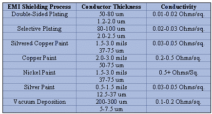
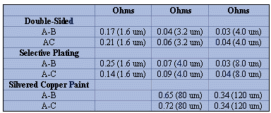
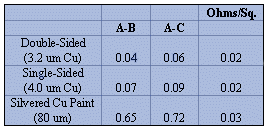
The conductivity of coatings can be measured using several different methods. The two most common means of determining conductivity include the ohms-per-square test method and the point-to-point measurement (Tables 5 to 7).
In the case of conductive shielding materials that are designed to address E-field and plane wave shielding, the importance of high surface conductivity increases significantly with the fundamental frequencies of device operation. In addition, the effects of the harmonics associated with these fundamentals increase the importance of determining both the conductivity of the coating and the uniformity of the conductive film across the entire surface of the part.
In production, conductivity testing becomes an important means for quality control of individual parts as well as for part-to-part testing of assembled enclosures. For plated coatings, ohms-per-square testing can also be used as an effective check on the actual thickness of plated metal films due to the uniformity and conductivity of the metal film itself.
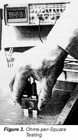
Ohms-Per-Square Testing
Ohms-per-square testing involves the placement of a probe on the surface of a part. This probe has two outside blocks of equal geometry and a space of equivalent dimension between the blocks (Figure 3). In general, the ohms-per-square test produces relatively ideal results for a given coating in that the proximity of the measurement is very close. Variability in readings will result from differences in the pressure applied to the surface by the inspector. In addition, variations in the surface topography due to variability in the conductor thickness, discontinuities in the coating, or as a result of the part roughness will also affect the final result.
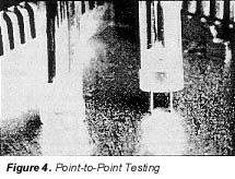
Point-To-Point Testing
Point-to-point conductivity testing is the most common means of evaluating the actual conductivity of shielding materials on production parts (Figure 4). This method utilizes two spring-loaded probes that are placed at the designated positions on the part or between two areas on mating parts (part-to-part conductivity). The conductivity between these points is then taken as the measurement. Point-to-point testing is an effective means of evaluating the consistency of a given conductive material across actual parts.
Shielding Effectiveness
The shielding effectiveness (SE) of conductive coatings can be evaluated using a variety of different methods. These include the dual chamber and the transmission line methods, and the newer coaxial transmission line test.
Dual Chamber/Transmission Line Testing
Shielding effectiveness testing as defined by the ASTM ES7-3 Standard evaluates and ranks alternative shielding materials on flat or planar surfaces. In this standard, the near-field region is evaluated using the dual chamber test method. The far-field region is evaluated using the transmission line test method.
Coaxial Transmission Line Testing
Comparative testing has also been performed according to the newer ASTM D-4935-83 test method. This method is designed to measure the SE of a planar material due to planewave and far-field EMI wave radiation.
Long-Term Performance
Product reliability and quality demands in today's electronic marketplace have placed increasing pressure on the material selection process. In the case of shielding materials, a major concern exists with the ability of alternative coatings to maintain their adhesion, conductivity and resulting SE over extended periods of time. Furthermore, the rapid growth in portable electronic devices, such as laptop computers and hand-held portable products like cellular phones, pages, sub-notebook products, etc., has increased the likelihood that a given product will be exposed to potentially aggressive environments.
Several test methods have been utilized to address this concern. These include the UL-746C accelerated temperature and humidity test, the 4/4/16 temperature humidity cycling test developed by IBM, the ASTM B-117 neutral salt spray test, environmental cycling tests that involve the introduction of bleed-in industrial gases to simulate different levels of aggressive industrial corrosive environments, and other types of accelerated tests that address very high and low temperature flow, fill speeds and pressures, and part design.
Summary
Conductive coatings technology has continued to evolve along with the changes in product design and the complexity of today's electronics. Any assessment of the current capabilities of conductive coatings must include not only the basic performance differences that exist between each coating type, but also the capability of the process to deal with key variables in product design. In addition, cost is always an important consideration in the selection process.
Acknowledgement
The authors would like to gratefully acknowledge the contributions of Apogee Plastics, Daytona Beach, FL, in the development of some of the electrical and shielding performance data included in this paper.
The Authors
Edwin Bastenbeck has been associated with Enthone-OMI since 1961, and is presently Research Manager in charge of research development for plating processes.
Brian Jackson is Marketing Manager for Enthone-OMI's electronics business in Europe. His specialty is electroless plating technology.
Peter Kuzyk is International Marketing Manager for Enthone-OMI. He has been associated with the finishing industry since 1977 in various positions.
Gary J. Shawhan is the Marketing Development Manager for non-PWB electronic applications at Enthone-OMI and has more than 10 years of experience in electroless plating and plastics plating.
Seleco, Inc., 8427 Zionsville Road, PO Box 68809, Indianapolis, IN 46268 Phone: (317) 872-4148 Fax: (317) 875-3276.