
A New Approach in Plant Physical Documentation and Information Management for Existing Facilities, Part II

Dr. Moh Hashemi, PE & David S. Reinhart
INOVx Solutions
Part I of this feature described the traditional manual approach to collecting plant physical documentation for plant redesign or retrofit applications and introduced us to laswer scanning and imaging as well as photogrammetry. These techniques are used in the creation of 3D CAD models for plant physical documentation. Part II presents an example of the work process, from things you need to consider from the outset to the benefits of using laser scanning and imaging, and photogrammetry.
The New Work Process
The laser scanning and photogrammetry work process includes a series of sequential phases for collecting data and describing the as-built condition of the facility.
Project Planning
During the project planning phase of the work process, the project needs are defined and outlined. The project team establishes the following parameters, which are essential to the success of the project.
- The boundaries within the facility requiring documentation
- The required level of accuracy
- The elements to be documented (steel, equipment, piping, conduit, etc.)
- The field data collection strategy and plan
- The required schedule for preparation and delivery of the physical database
Generally, a site visit is required for collecting the above information prior to the documentation of any plant physical data. During this visit, a digital and/or video camera is used for capturing the scope of the project. The degree of completeness and the required level of accuracy, along with other notes and remarks, are noted and combined with the digital photos. A scope definition document is delivered at the completion of this phase of the project.
The emphasis in the project planning phase should be on the completeness of the plant physical documentation and not the potential degree of the CAD modeling requirement. A complete physical database with a powerful browser can adequately meet the need of many engineering, operation and maintenance applications without the need for any modeling. If a CAD model is desirable, one can be developed to suit project requirements from the completed physical database without the need for additional plant documentation.
Site Planning
During the site planning phase of the project, a plan will be prepared by the plant documentation team at the facility before any plant physical documentation takes place. This plan considers requirements for site access, access to the specific areas of the facility, special clothing or protective gear, needs for scaffolding or other types of equipment (e.g., man-lifts), requirements for safety training, and any other considerations needed while the personnel are on site. A primary focus revolves around the safety of the personnel who will be performing the work and other personnel in the areas of the facility in which they will be working.
Site documentation planning is a key step in assuring the accuracy and degree of details needed for various applications are met. The right tools and technologies are selected to meet the requirements of the scope definition document, i.e., laser scanning, photogrammetry, or both.
Field Documentation
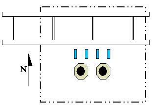
Next, the field documentation involves the use of skilled personnel and specialized equipment at the facility to collect the required data for development of the physical database. The deliverable for this phase of the project consists of (1) surveying data for the targets that serve to precisely locate the various components of the facility in site coordinates and (2) the clouds of points and stereo photos of the facility components. A high-precision theodolite is used for surveying, precise array camera equipment is used for taking photographs, and a laser scanner is used to collect the clouds of points in this phase of the project.
It is commonly assumed that the degree of accuracy achieved is dependent on the selection of either laser scanning or photogrammetry technologies. In reality, the most important element is a solid and proven work practice implemented by an experienced team. The team must know how to break a plant into small areas and effectively place surveying targets strategically throughout the facility. They must follow strict work practices to meet project accuracy and level of detail requirements of a project. Based on the density and situation of the specific area being documented, the team must utilize the appropriate technology and approach to data collection. For these reasons the field team experience and their documentation practices play a much more important role in achieving the project objectives than the type of technology used.
Analysis - Development of a Physical Database
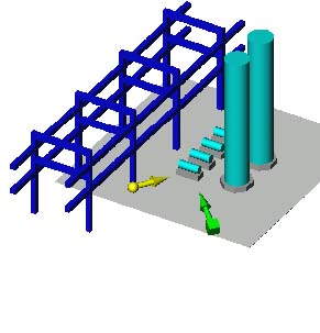
The analysis phase of the project involves (1) transfering the individual clouds of points and stereo photos into proper plant coordinates using the surveying coordinate data obtained during the site survey, (2) placing the transferred laser scans and photogrammetry images in a database and (3) creating a simple CAD model for navigating and exploring the plant's major features. The position and view angles of the various laser scans and camera positions are clearly marked in the navigation CAD model. Once combined, this data is referred to as the plant's "physical database" and is the deliverable for this phase of the project.
The manipulation of raw data should be minimized during the creation of a physical database. Mathematical techniques can be used to make clouds of points and stereo photos match closely with the surveying results. These methodologies are known under various labels such as "warping" of laser scans and "bundle adjustments" of photogrammetry images. These techniques can in fact appear to improve the accuracy in some areas. The major drawback is not being able to clearly and specifically define the accuracy of a data point retrieved from photogrammetry images or a laser scan after modification. A good system should provide the user with a confidence level for each data retrieval. Designers can make necessary adjustments and contingencies if they know the degree of uncertainty. However, incorrect assumptions on the accuracy of data may result in poor design.
"Analysis" is the term given to the creation of the photogrammetry portion of the physical database. Stereo photos of the facility are first created in a database then viewed and precisely linked to the survey targets visible in the images. With each stereo pair created quality assurance levels are provided for the survey used and the confidence of triangulation in the pair.
With laser scanning technology as it stands today, the clouds of points are generated in an arbetrary coordinate system and must be adjusted prior to utilizing them for data extraction. The process known as "Registration" is the stitching together of the clouds of points with best fit algorithms. This methodology connects the clouds into a single reference coordinate system. However, this process can introduce rotational error due to the "best-fit" approach. The drawback in the technology can be overcome with the use of 3D surveying targets combined with what is referred to as "Global Registration" where each laser scan contains four to five 3D survey points which are used to precisely adjust the cloud of points to the plant coordinate grid. Each cloud of points remains a unique data set and resides in plant coordinates.
Referencing all the project laser scans (clouds of points) into a single data set is generally promoted in the industry as a way to view and navigate through the collected scan data sets. However, in most instances, simultaneously referencing several clouds of points for a complex facility will result in a discontinuous and ambiguous 3D representation. In addition, walkthrough of the registered clouds of points is slow and cumbersome due to the large size of the merged scan data file. This problem is increased dramatically if the data is viewed in conjunction with intensity and texture mapping of the clouds of points. For these reasons, a single cloud of points as viewed uniquely and directly from the laser scanner is the most effective way to explore plant details. Navigation through the clouds of points may be performed by referencing the CAD navigation model in the database browser.
The physical database must be accompanied by a powerful browser. The browser provides the user with the ability to perform the following tasks:
- Explore the plant by reviewing the simple CAD navigation model.
- Explore the plant details by selecting the appropriate views captured by clouds of points and stereo photos.
- Obtain the coordinate position of any point in the photogrammetry images or a laser scan.
- Measure any distance between two points using the clouds of points and stereo photos.
- Mark and identify elements and relate the objects to the CAD model, stereo photos or cloud of points.
Scoping the CAD Modeling
During the scoping the CAD modeling phase of the project, the required extent of a subsiquent CAD model (2D or 3D) will be defined. The clouds of points, stereo photos, and regular photo and video images can be used for defining the portion of the project requiring CAD graphics.
Typically, the effort for field documentation and analysis phases are significantly less than the effort for the modeling phase of a project. Therefore, the scope of the model should be fitted for a specific purpose and tailored for project needs.
A simple CAD model that includes major equipment, structure and civil aspects of the plant is a very effective tool during the conceptual design of a revamp and retrofit project. A detailed model in the vicinity of each tie-in point can be added to a conceptual model for a simple revamp and retrofit project. A fully detailed 3D model is most ideal for a complex revamp and retrofit projects. These and other factors should be considered when scoping the modeling effort.
CAD Modeling
The CAD modeling phase of work involves development of the model containing the CAD symbols representing the facility components with a very high level of accuracy. As each set of cloud of points or stereo photos are modeled, the CAD elements representing piping, valves, equipment, HVAC, concrete, steel, and other components are developed and placed in the model using the 3D coordinate information for placement, orientation, size, and relative position to each other. In addition to the development of the model, information can be added to the model, if available. This includes equipment tag identifiers, piping specification or other information that may be desired.
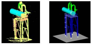
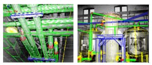
Model verification and quality assurance are an integral part of the analysis phase to ensure the accuracy of the developed model, the position of the modeled components, the orientation of the modeled components, size, and completeness of the model itself. This process consists of a series of model reviews or "walk-throughs". The completed computer model is overlaid on the high-resolution stereo photos and cloud of points at the graphics workstation to visually verify each of the quality assurance parameters. In addition to the visual overlay verification, the software contains an expert subsystem that has the ability to analyze the clouds of points and stereo photos.
Visual measurment verification aids and accuracy deviation dialog information is available and utilized to provide the user with statistics and information indicating the accuracy with which the model has been developed, and areas where the potential for error exists. These steps ensure the delivered model meets or exceeds the required level of accuracy initially specified for the project.
Engineering, Simulation and Information Management
The final step of the documentation process is the transfer of the generated model to the target CAD system for engineering, simulation and information management purposes. This process moves the completed laser scanning and photogrammetry model from the graphics workstation into the 3D CAD design system where the model can be utilized by various disciplines to add new designs to the model, confirm fit-ups, perform equipment removal studies, routing studies, construction process reviews, space envelopes, obtain precise measurements of the "as-built" condition of the facility, and plan operation and maintenance activities.
Commercial CAD systems provide a powerful design environment and are very effective design and management tools when a detailed model of the existing facility is available. An alternative approach is to provide the full capability for importing new CAD designs into the browser of the laser scanning and photogrammetry physical database system. This hybrid system integrating laser scans, photogrammetry images, survey data and new design provides an effective and efficient environment for documenting the ongoing modifications and plant activities in an existing facility.
Conclusions
The use of plant documentation using laser scanning and photogrammetry technologies yields several direct and immediate benefits for a revamp and retrofit project. The first and most benefits are the reduction in cost and scheduling of performing the site data collection. Traditional methods of performing site documentation require the use of several personnel to manually measure and sketch the as-built condition of the facility. This manual process is time-consuming, frequently contains errors, and results in minimal amounts of useful field data being collected and shared.
The methodology outlined in this paper, on the other hand, collects large volumes of very accurate and complete information. The data is collected into a single physical database where plant geometry and information may be extracted by all disciplines through a browser. At the same time, the actual documentation of the site data can be collected more efficiently and is found to be approximately the same as the cost of the manual process. The data may be translated into highly accurate visual CAD models that can be manipulated, analyzed, and extensively used in revamp and retrofit projects or plant operation and maintenance applications.
Other direct benefits of this integrated process include:
- The high level of completeness and accuracy achieved in documentation will clearly reduce the potential for downstream rework in the field during the construction phase of a revamp and retrofit project or operation and maintenance activities.
- The field data collection associated with laser scanning and photogrammetry inherently contains safety considerations for personnel. Personnel can maintain safe distances from hazardous materials, plant equipment, or other hazards. Minimal or no human contact is required with hot, cold, or hazardous objects in the facility.
- The integrated work process can also be used during the shop fabrication process to confirm that the fabrication of critical components will have the proper fit-up in the field. This process can prevent costly delays during construction by using the models of the as-built condition of the facility and the "as-fabricated" components to confirm dimensions, rotations, nozzle locations and orientation, fit-up, etc.
- The physical database of an existing facility containing clouds of points and stereo photos serves as excellent documentation of the "as-built"condition of the facility containing details that may not have to be modeled, yet are available for viewing and extracting measurements.
- The physical database permits only the areas of current interest to be modeled. If it is anticipated that additional areas may be needed at a later date, the site survey team can collect the data, but delay or defer the development of a CAD model until it is confirmed that one is required and do so without needing additional visits to the facility.
- The physical database can be translated to the 3D design system, permitting design work to proceed immediately with accurate, as-built data and plant configuration. This minimizes or eliminates questions from the engineering perspective related to the as-built condition of the facility and brings the plant to the engineering office.
- Once the 3D model has been moved to the target 3D design system, orthographic and isometric drawings can be extracted from the model to provide new and current documentation reflecting the current "as built" condition of the facility.
- The resultant 3D model has the potential for becoming "living documentation" of the facility if properly maintained with the current facility configuration over time. This minimizes the future potential costs for revamp or retrofit work that may be required over longer duration of time. An alternative method is to use a 3D model of the new design in conjunction with clouds of points and stereo photos included in a physical database.
- The 3D model may be used for interference checks and constructability analysis. It facilitates the optimization and detailed planning of the installation and removal of plant components using model graphics.
- Detailed planning and training of plant and craft personnel can be performed using the 3D model, thereby potentially reducing the time normally required for plant operation and maintenance activities.
- The physical database and 3D models could provide the basis for development of a larger information management system that contains detailed design, maintenance, or other information critical to facility operations and maintenance.
There are many arguments for using 3D CAD models in your revamp and retrofit – or even plant design – projects. If you do decide to go this route, evaluate software programs closely to determine which one is best for your plant.
INOVx Solutions of Irvine, CA, provides visualization solutions for plant documentation and information management. The company employs a proprietary combination of photogrammetry and laser scanning technologies to produce scalable, fit-for-purpose databases and models of a plant's "as-is" physical condition.
For more information, contact Moh Hashemi, Ph.D., P.E., President, INOVx Solutions, 18011 Sky Park Circle, Ste K, Irvine, CA 92614. Phone (949) 250-6524; Fax (949) 250-6526; Email: mhashemi@inovx.com.